Subsystem #11
Lifeboat
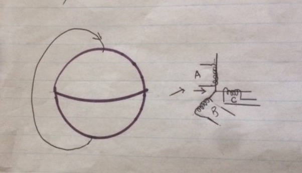
In above diagram, on the left diagram, note the earth and a line of the earths’ magnetic field which starts at the South Pole and traverses North past the equator and on to the North Pole. The arrow on the mag field line shows the direction of the field as it approaches the North Pole from the South.
On the right diagram, note the 3 coils A, B, and C , representing the 3 Lifeboat magnetometer coils. Assume all 3 angles between the coils support, (A to B, A to C, and B to C) are 90 degrees which makes them orthogonal to each other. Then, from our Electric and Magnetic Fields 101 course days, if a magnetic field is present in a coil, voltage will be output on the coil, in this case on the two lines of each coil. If the field is EXACTLY parallel...
LIFEBOAT SUBSYSTEM
The Lifeboat Subsystem contained its’ own attitude control hardware and gas supply, batteries, and a command subsystem which responded to uplinked Lifeboat KIK and KIKZEKE commands from the ground to accomplish RV deboost. It had a three axis magnetometer (for earths’ magnetic field sensing) unit which provided the primary input used in positioning the RV for deboost, as will be explained below. It provided backup RV recovery capability, when either the OCV Stabilization or Command Subsystem had suffered an anomaly that prevented their use for recovery operations. Lifeboat was designed to take, at worst case, a randomly tumbling vehicle which might be venting control gas due to an attitude control gas leak or experiencing a gas valve stuck open, capture the control of the vehicle, point it in the correct direction to deboost the RV and issue the commands to accomplish the deboost.
The Lifeboat RV deboost activity was initiated by uplinked Lifeboat commands setting Lifeboat Realtime Mode (by sending usecure KIKZEKE 26\25 and secure KIK 31) or Lifeboat Next Orbit Mode (by sending unsecure KIKZEKE 26\21 and secure KIK 31). This started a 90 second timer either immediately for LBRT or 5400 seconds (90 minutes) later for LBNO.
During the 90 second timer period, one of the first items executed was disabling of the primary attitude control gas valves by closing a valve in line feeding the gas to the primary attitude control gas valves, to stop any more primary gas valves from venting gas and allow the lifeboat attitude control system to gain attitude control, and align the vehicle to the desired orientation for RV deboost.
Then, using the 3 magnetometer outputs, namely the voltage outputs of the 3 axis magnetometer coils A, B, and C (seen in the right hand part of the figure above) as they moved through the earths’ magnetic field, Lifeboat attitude control valves opened and moved the vehicle and magnetometer C until it reached a maximum value, and magnetometer coils A and B values read 0 volts. That then meant those 2 magnetometer coils (A and B) were perpendicular to the earths magnetic field, and the third one (C), and read some maximum voltage, was parallel and aligned with the centerline of the vehicle, and with the earths’ magnetic field.
I believe this use of the magnetometers was initiated after the vehicle came over the North Pole, then headed South towards the South Pole, and, when it arrived south of the North Pole near the Kodi tracking station, the magnetic field was pointing about 56 degrees down toward the North Pole. This angle is very similar to the pitchdown angle commanded when executing the RV deboost via the OCV Command Subsystem near the Kodi tracking station. See the RV Subsystem section part of this writing for details on RV deboost via the OCV Command Subsystem.
With the vehicle aligned with the earths’ magnetic field and pointing at the North Pole, commands from Lifeboat were then issued to execute a Cut and Seal command, to seal the RV and make it watertight, followed by issuing a sequence of 4 separation necessary related commands replicating the OCV commands (Prearm, Arm, Transfer and Separate) to the RV, which, after execution of the Separate command, hands the rest of the RV recovery commanding over to the RV itself, in the form of outputs from the RVs Separation, Rocket and Recovery programmers. NOTE: In forcing one (the C coil) magnetometer to output a maximum voltage, and the other two coils (A and B) to output 0 voltage by firing valves to reorient the vehicle attitude to obtain those readings, it was possible that the vehicle could be pointed 180 degrees AWAY from the North Pole, rather than at the North Pole. To correct that, the voltage polarity on the magnetometer output was sensed, and if the value showed the vehicle was pointing away from the North Pole, a switch was made to cause the vehicle to be rotated 180 degrees to point the correct direction.
LifeBoat RV deboost commanding was very similar to that of the OCV RV debost commanding.
Comparing the Lifeboat RV deboost scenario with that for the OCV deboost scenario, note that they accomplish the same thing, i. e., orienting the OCV to the attitude needed for RV deboost. The one difference is HOW the OCV was oriented to the Separation attitude. OCV deboost orientation employed Yaw Reverse and PitchDown commands for orientstion, whereas the Lifeboat deboost orientation employed magnetometer sensing for orientation.
I seem to recall that the OCV Telemetry, Tracking, and Command (TT&C) hardware could be commanded on via the LifeBoat transmission and execution of a secure KIK32 command. This provided a means of reacquiring uplink and downlink capability when, as an example, the OCV command memory containing TT&C commands for stations was erased and not reloaded.
Taking a proactive tactic that “it is worth a try; we have nothing to lose and something to gain” in deboosting the OCV right after RV deboost to get it out of space so that space junk tracking assets don’t have to monitor decay of the OCV, I believe that a few times an OCV deboost sequence was executed right after the Lifeboat RV deboost was completed. This was done while the LifeBoat attitude control subsystem was still maintaining the OCV pointing, and had not depleted all of its attitude control gas supply. Recall that the OCV attitude control gas supply was disabled during the LifeBoat RV deboost. So, if the OCV Command Subsystem was still okay, a command message was generated which contained several Engines On commands, with the command timetags for each set of Engine On commands spaced apart such that the first timetag was shortly after RV Separate. Then, shortly after the time of RV deboost and verification of that event, the selection of a set of OA Engines On commands was loaded in the OCV Command memory, for readout and execution a short time later to deboost the OCV if the attitude was still correct for the deboost of the OCV, I believe that multiple sets of OA Engines On commands were created, with timetags on each set being slightly larger than the first set, whose timetags were a few seconds after the RV Separate command timetag. Subsequent timetags on the following blocks were increased 15 or 20 seconds on each set.
One other LifeBoat related item that may be of interest to some readers is that I recall attending some meetings investigating the feasibility of using a Gambit vehicle to perform mission operations in a different part of the World. The orbit would have been vastly different, and, as I recall, the ability to use the backup LifeBoat RV deboost capability was more complicated, in view of the fact that the magnetometer related processing logic would have needed modification by adding bias’s to the magnetometer values used to point the vehicle properly for RV deboost. The plan never was executed for several reasons; LifeBoat impacts were only one of the problem areas.
I think that the KIK 31and KIK 32 were secure commands requiring a matching secure key pattern uplinked to match a secure pattern in a KIK plug installed on the Lifeboat package before launch.
Go to Thanks.